

Horizontal Vessel Piping Stress
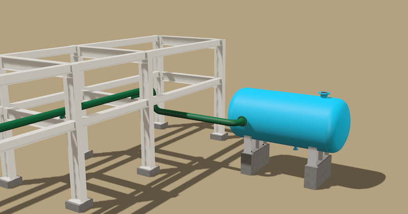
A piping system connected to a horizontal pressure vessel. This is a simple design that you can see many times in your piping journey. Now, let’s take a closer look together.
First, we look at the process details of the pipe. Normally, the first step should be to consult the process engineer to understand the operating and design conditions, and if there are any critical or noteworthy details worth analyzing, we should take note of them. This is crucial for conducting our analysis and creating the load cases. However, since this is a training video, we are simply listing these values here.
The first thing we need to do is, list all the input values of the pipe in an Excel sheet. I would like to emphasize that this design is not real and has been entirely created for this training.

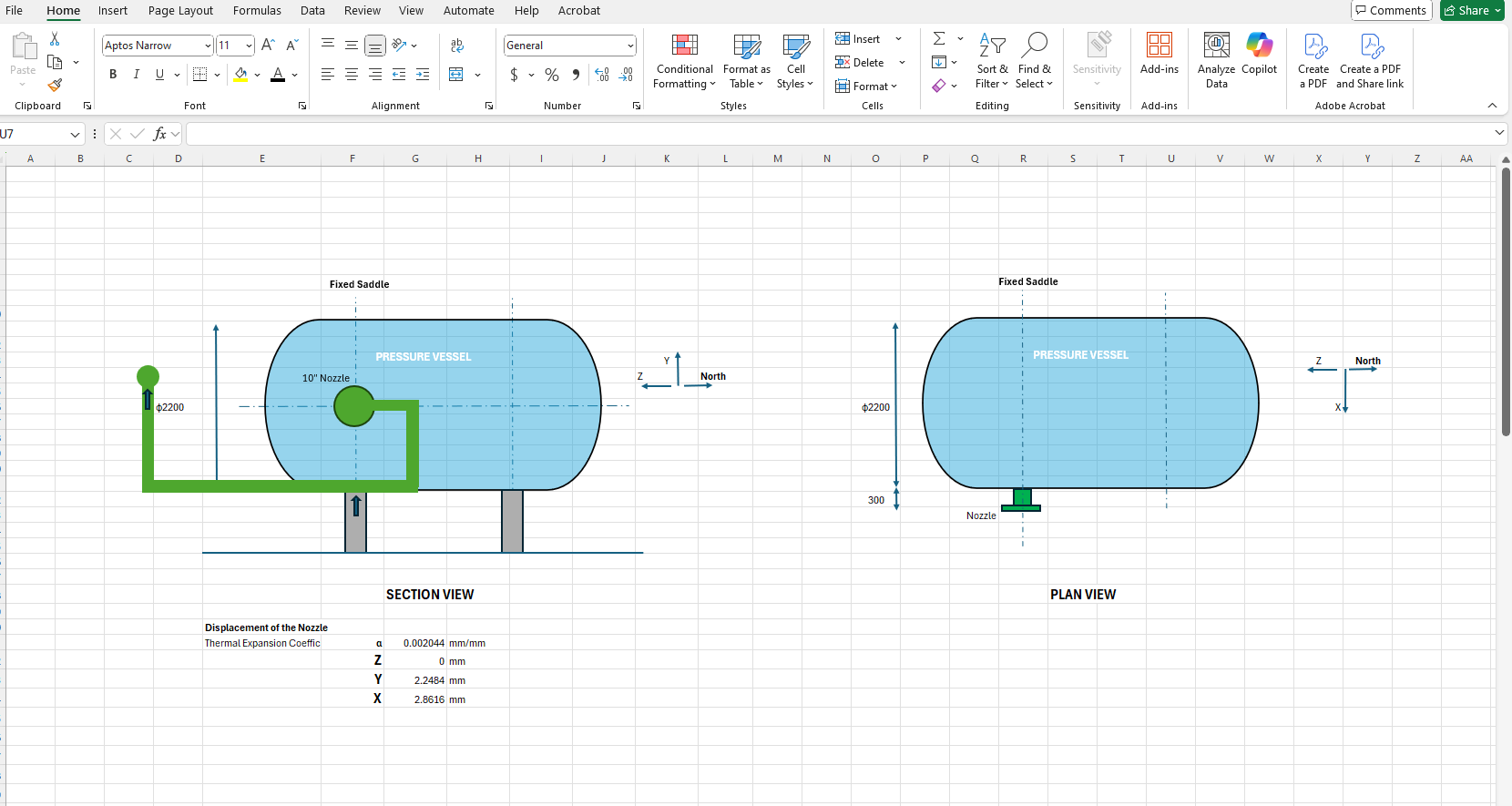
Let’s now take a look at the thermal expansions of the equipment. You can see the thermal expansions for the nozzle. Here, the thermal expansion of the nozzle has been calculated using the expansion coefficient for the material of the equipment.
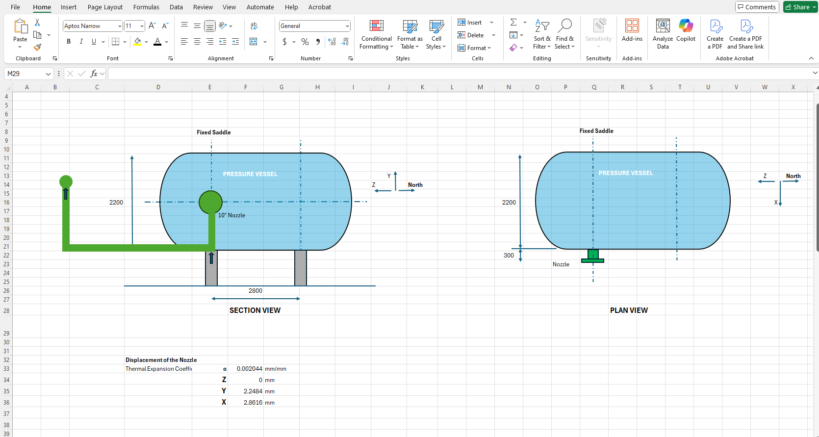
Let’s examine the thermal expansion of the pressure vessel in 3D across the x, y, and z coordinates. We need to determine the location of the equipment’s fixed saddle. This is usually determined by the piping stress engineer. However, it is necessary to communicate with the equipment manufacturer for this. If we need to design according to existing equipment, we should perform the piping stress analysis based on the current situation. For now, let’s calculate and record the thermal expansions for both scenarios.
The nozzle will expand in three axes based on its location. First, the equipment will expand along its own axis.

Since the project’s north direction is in this direction, let’s always consider the direction opposite to the project’s north as the positive z-coordinate. In this case, if the fixed saddle is far from the nozzle, there will be an expansion in the positive z-direction. However, if the fixed saddle is on the same axis as the nozzle, there will be no expansion in the z-direction.
In the first scenario, let’s assume that the position of the fixed saddle is the one farthest from the pipe rack. In this case, the expansion in the +z direction is calculated by multiplying the expansion coefficient by the distance between the saddle and the nozzle, which is 2800 mm.
Next, let’s look at the y-axis, i.e., the vertical expansion. We always consider the +y direction as the positive vertical direction. In this case, for the equipment’s expansion calculation, since the nozzle is located in the middle of the equipment, we multiply the vessel’s half-length, 1100 mm, by the expansion coefficient.
Finally, let’s examine the x-axis. When looking at the plan view, the nozzle axis aligns with the x-axis. For the expansion here, we also multiply the radius of the equipment by the thermal expansion coefficient to find the thermal expansion. This is because we assume the expansion originates from the center of the vessel.

Now that we’ve determined the thermal expansions of the equipment, let’s proceed with the piping stress analysis.
Caesar II Analysis
We will discuss four scenarios here and try to explain their pros and cons to you using the Caesar II outputs.
Scenario 1
In the first scenario, we have positioned the equipment’s saddle far from the pipe rack. In this case, we will observe the loads applied to the nozzle in the existing design. Additionally, we placed a guide on the first support of the pipe on the pipe rack. Let’s see what happens to the nozzle and the pipe under these conditions.
After inputting all the data and building the model in Caesar II, we run the analysis after configuring the settings.

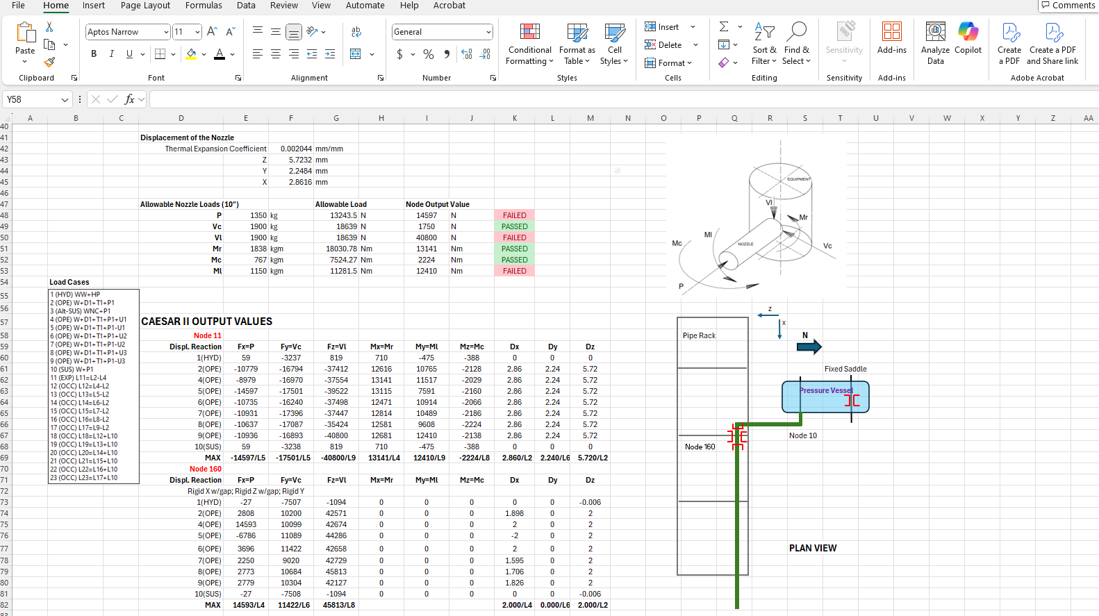
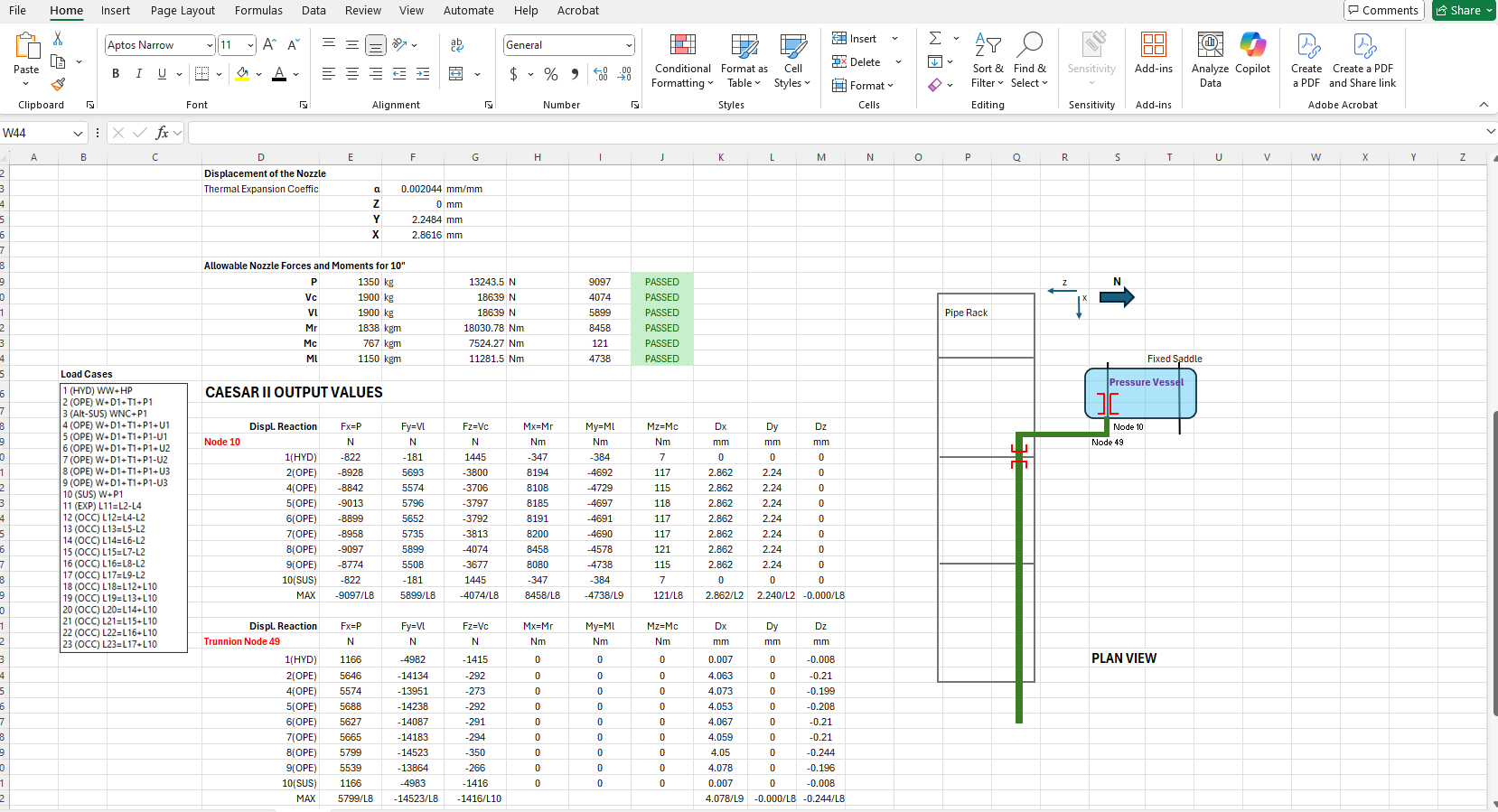
Now, let’s evaluate the results using the Restraint Summary.
Node 10 is the number assigned to the nozzle. Looking at this node, we see that the nozzle and the guide are interacting along the z-axis, which causes excessive loads on both the nozzle and the guide.
Therefore, placing a guide on the first pipe shoe on the pipe rack was an incorrect decision.
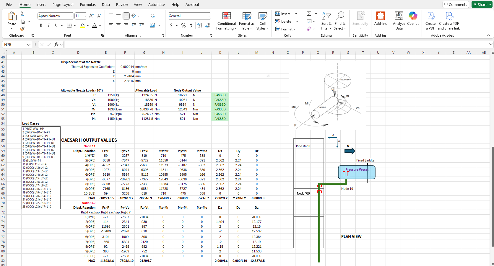
When we remove the guide, you can see the results of the updated scenario.

Scenario 2
Now, let’s change the position of the fixed saddle. In this case, there will no longer be any displacement of the nozzle in the z-direction. When we input this scenario into Caesar II, we observe that the moments and forces on the nozzle are below the allowable limits.
Scenario 3
Let’s now examine the case where the pipe exits the nozzle and turns downward. We add a trunnion support to the elbow of the line that goes downward from the nozzle and evaluate the results.
If we make the downward leg length of the pipe the same radius as the pressure vessel, the pipe will behave similarly to the pressure vessel under operating conditions. This way, we should not see any overstress on the nozzle.
You can observe the thermal expansions under operating conditions. It can be seen that the thermal expansion of the nozzle and the thermal expansion of the pipework together.
If the vertical leg of the pipe is of a different length, it will lead to stresses or excessive loads on the nozzle. If the pipe is longer than the equipment, the nozzle and the trunnion will influence each other in opposite directions, causing excessive loads. Similarly, if the pipe is too short, the thermal expansion of the equipment in the +Y direction will force the entire piping system to carry the load under operating conditions, again resulting in overload on the equipment nozzle. Therefore, this issue must be carefully considered and analyzed in detail.
Scenario 4
Another approach is to direct the pipe northward after the nozzle, then make a downward turn to continue towards the pipe rack.
In this design, it would be more appropriate to place the first pipe support in line with the fixed saddle. This is because the thermal expansion of the pipe will align with the thermal expansion of the equipment. Similarly, seismic effects in the z-direction will not create any moment on the nozzle.
When we run this analysis, we observe that the moments and forces on the nozzle are below the allowable limits. However, we also notice that the first support is subjected to slightly higher vertical loads than usual. This is due to the interaction between the nozzle and the support.

Conclusion
Now, let’s compare all these analyses and discuss our observations.
The output values in the third and fourth scenarios are below the allowable limits. However, using too many elbows in the piping is not cost-effective, but it could be used in high-operation-temperature conditions.
In the first scenario, the restraint we used (the guide) significantly increased the forces on the nozzle to an excessive level.
The design and analysis results in the second scenario, which is the same as the first one except for the guide, demonstrate the most optimal solution. In both positions of the fixed saddle, the pipe, and the nozzle do not experience overstress or overload.