

Expansion Loop Calculation - CAESAR II
Sometimes, fluids need to be transferred from the far side of the plant. We can’t leave the long-run piping without restraints, especially since the lines contain high-temperature fluids in the low ambient temperature environment.
The restraints on the long-run strait piping are crucial. However, due to thermal expansion and seismic events, the stoppers take excessive loads, making it impossible or expensive to design a special support.
By the expansion loops, we can reduce the stopper’s load by sharing. This will allow us to control the line better.
The second reason for the expansion loop requirement is to minimize thermal expansion on the farthest side from the stoppers. This has two benefits. First, we don’t need to consider the flexibility of branch connections, which could increase the cost if we have multiple branches. Second, if we use an expansion loop on the line, we don’t need to worry about the length of the pipe shoes on the farthest side from the stoppers.

The last one. Consider that two pipe racks are perpendicular to each other. If we put the pipe stopper to the natural zero point, the expansion on the corner will be formed like this. Any guide requirement here, due to the seismic effect, will contradict with this stopper. This is why it is important to use the expansion loop to manage expansion with the help of restraints. Without it, the piping system may collide with adjacent lines during normal operation and occasional conditions.
Let’s analyze the long-run pipe and expansion loop design on Caesar II.
Let’s have a look what happens if we make anchor for the both side of the line. For this, we need enter
CAESAR II STUDY
Before we start, let’s outline the input values in this example.
Pipe diameter: 6 inches
Pipe thickness: Schedule Standard
Operating temperature: 200°C
Operating pressure: 20 barg
Ambient temperature: 0°C
This piping has 100mm thick insulation.
We have entered all these input values. First, assuming both ends are anchored, let’s analyze the loads at the anchor points.
As seen, overstress occurs along the pipeline. The axial load at the anchor points is approximately 1.8 million N, and these forces act against each other, meaning they push against one another.


Therefore, we cannot leave it as it is.
Anchors are not very realistic for straight pipelines. When we remove the anchors, we can observe the expansions at the pipe ends when we remove the anchors due to thermal expansion.
After conducting the analysis, we observed that, under operating conditions, the pipe ends undergo significant expansion movements.
Leaving these expansions as they are would require additional expansion loops, especially in branch piping design. Therefore, designing an expansion loop on the main line is much more economical.
Now, let’s design a 5-meter expansion loop. The length of 5 meters is chosen solely because it aligns with the width of the existing pipe rack. There is no particular reason for this specific length. A longer expansion loop could be utilized, but it would necessitate additional steel structures. Therefore, an optimal design should be selected.
After running this analysis, we see that the expansion loop has reduced the axial load on the previously anchored straight pipe to approximately 9000N. This demonstrates how much axial loads can be reduced using an expansion loop. Thus, a loop length of around 5-6 meters will be sufficient.


Normally, if we do not use an expansion loop, we can place a stopper at the natural zero point instead of anchors. However, this would also cause some of the issues mentioned earlier due to pipe-end expansions.
We can reduce the operational loads on the stoppers by increasing the length of the expansion loop. When we do this extension, we should also check the deflection at the middle of the expansion loop's leg. Adding a node in the middle will make this more accurate. In our example, the deflection is 3,5 milliliters at sustained case, which is acceptable because it is less than 12.5 mm.

DEFLECTION AT SUSTAINED CASE - SHOULD BE LESS THAN 12,5mm
Now, let’s assume this pipeline continues over another pipe rack that is perpendicular to the existing one. In this case, if we don’t use an expansion loop on this type of long-run pipe rack, the expansion level at the turn will be high at operation, and the line will clash with the nearby piping lines.
Also, if we use guides on the turn, the line will be subjected to overstress because of the contradiction between the stoppers and guides.
So, the ideal solution is to design an expansion loop on each long-run pipe rack. This will give us the best control on the piping design.


Expansion on X direction at the corner

Proper piping and expansion loop design with two pipe racks perpendicular to each other
Finally, let’s compare the hand calculation with our design. In our Caesar model, we designed 6 meters long expansion loop.
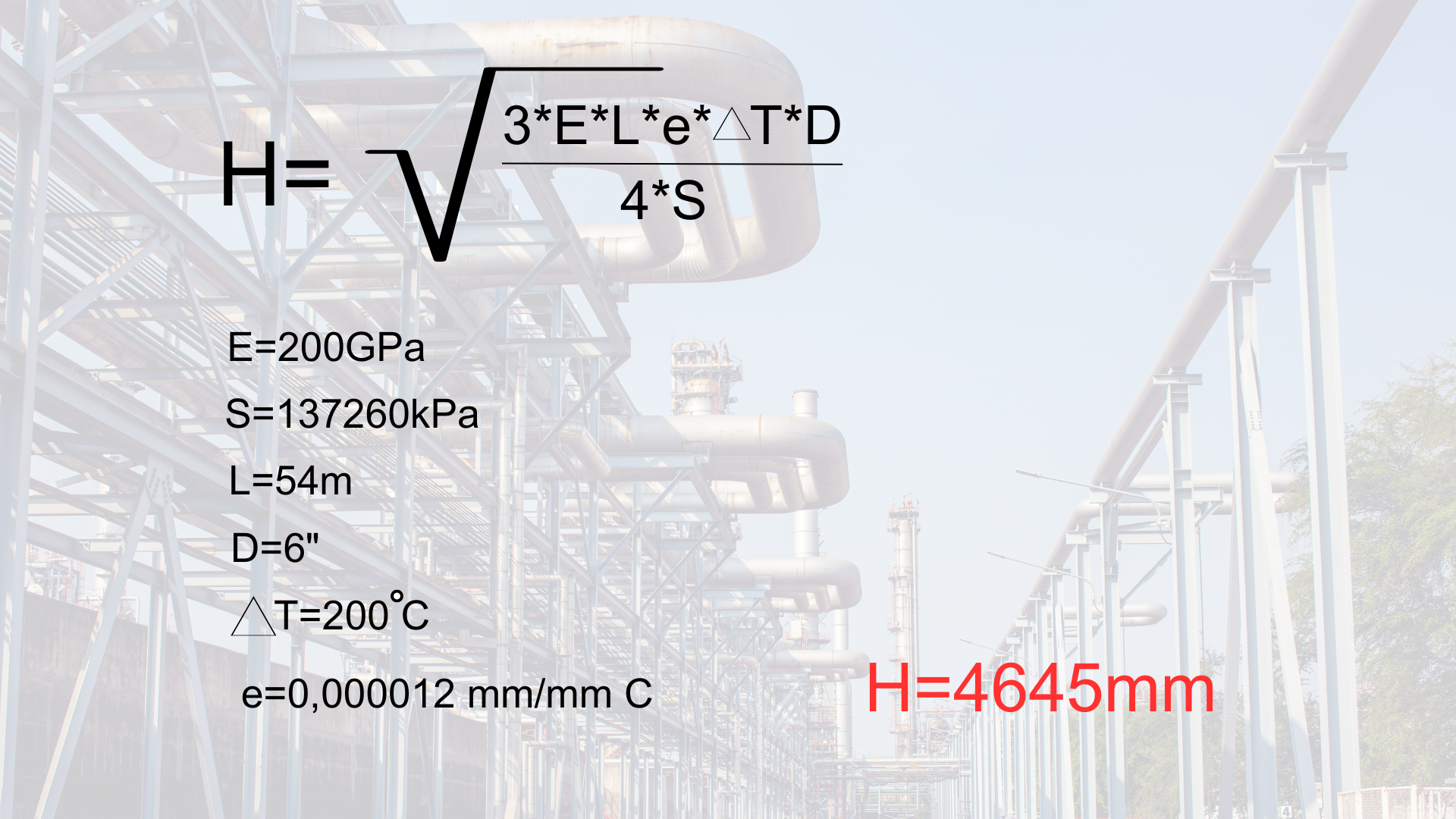
Our formula gives us a 4.5-meter expansion loop. So, a 6-meter-long expansion loop design is sufficient.