Managing a Piping Design Office: A PMI-Aligned Approach
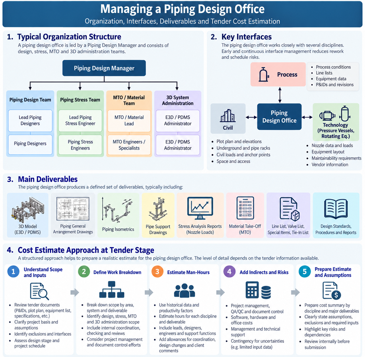
Managing a piping design office is not simply about producing drawings, stress calculations, material take-offs, and 3D models on schedule. A successful piping design organization must coordinate several specialized teams whose outputs are highly dependent on one another.
A typical piping design office may include piping designers, piping stress engineers, material engineers, 3D model administrators, and their respective discipline leads. Although these groups perform different functions, they ultimately contribute to the same engineering deliverables.
This blog presents a practical approach to managing such an organization using project management principles aligned with PMI practices.
1. Typical Piping Design Office Organization
A practical organizational structure may look like this:
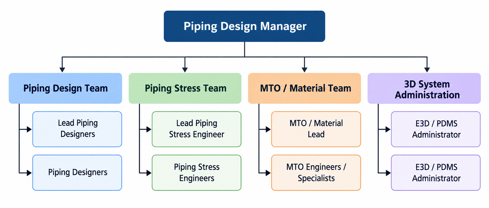
The Piping Design Manager should not attempt to directly control every designer and engineer. The manager's role is to manage the system, while the leads manage the detailed technical execution within their teams.
This distinction becomes increasingly important as the size of the design office grows.
2. Define Roles and Responsibilities Clearly
One of the first management requirements is to establish clear accountability. Every important deliverable should have a clear owner.
A practical tool is a RACI Matrix:
R – Responsible: Who performs the work?
A – Accountable: Who owns the final result?
C – Consulted: Who must be consulted?
I – Informed: Who needs to be informed?
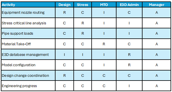
RACI Chart
Every important deliverable should have a clear owner.
Without clear ownership, problems frequently fall into the gaps between disciplines.
3. Manage Interfaces, Not Only Departments
One of the biggest mistakes in engineering management is managing each department independently.
The real management challenge lies at the interfaces.
Consider a simple piping system:
Process → Piping Design → Stress Analysis → Supports → 3D Model → MTO → Procurement → Construction
A piping designer may complete the routing, but the stress engineer may subsequently request flexibility changes.
That change may affect:
pipe routing,
support locations,
steel structures,
nozzle loads,
MTO quantities,
insulation requirements,
accessibility,
3D model,
drawings and isometrics.
Therefore, the manager should focus heavily on interface management.
4. Establish an Engineering Deliverable Register
A piping design office should operate against a controlled list of deliverables.
Depending on project scope, this may include:
Plot Plans
Piping General Arrangement Drawings
Equipment Layouts
3D Model
Piping Isometrics
Pipe Support Drawings
Stress Analysis Reports
Stress Critical Line List
Nozzle Load Reports
MTO Reports
Specialty Item Lists
Tie-In Lists
Valve Lists
Line Lists
Material Requisitions
Model Review Reports
Each deliverable should have, at minimum:
Owner → Planned Date → Actual Progress → Review Status → Client Status
This becomes the engineering team's equivalent of a project control system.
The manager should therefore avoid relying purely on statements such as:
“Design is approximately 80% complete.”
An 80% figure means very little unless it is connected to measurable deliverables
5. Use a Work Breakdown Structure
PMI principles emphasize breaking project scope into manageable components.
The same philosophy works extremely well for piping engineering.
For example:
1. Piping Engineering
1.1 Area A
1.1.1 Equipment Layout
1.1.2 Piping Layout
1.1.3 Stress Analysis
1.1.4 Pipe Supports
1.1.5 Isometrics
1.1.6 MTO
1.2 Area B
1.2.1 Equipment Layout
1.2.2 Piping Layout
1.2.3 Stress Analysis
1.2.4 Pipe Supports
1.2.5 Isometrics
1.2.6 MTO
1.3 Utility Area
1.4 Pipe Rack
This allows progress, manpower and priorities to be tracked by physical area or system rather than through a single overall percentage.
For large projects, a combination of Area + System + Deliverable is often particularly effective.
6. Planning and Resource Management
Effective resource management starts with understanding the actual engineering workload. The Piping Design Manager should establish a manpower plan based on the project scope, schedule, deliverables and complexity.
The workload can be estimated using measurable quantities such as:
Number of lines and piping isometrics
Number of equipment items and tie-ins
Number of pipe supports
Number of stress-critical lines
Number and complexity of project areas
3D model and MTO requirements
These quantities can then be converted into estimated man-hours using historical project data and productivity norms. The resulting workload should be compared against available resources and the project schedule.
However, manpower alone does not show whether the team is performing effectively. The manager should establish a small number of Key Performance Indicators (KPIs) at the beginning of the project.
Typical KPIs for a piping design office may include:
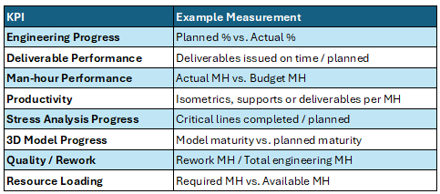
Key Performance Indicator
For example, if engineering progress is 55% actual against 65% planned, while actual man-hours are already above budget, this indicates more than a simple schedule delay. It may point to low productivity, excessive rework, insufficient input data, design changes or inefficient resource allocation.
Therefore, KPIs should not be used only for reporting. Their main purpose is to provide early warning signals for management action.
A good Piping Design Manager should regularly ask three questions:
Are we producing what we planned?
Are we using the man-hours we planned?
If not, what corrective action is required?
This creates a direct connection between planning, manpower, productivity and project performance.
7. Establish a Communication Structure
PMI places considerable emphasis on effective communication, and this is particularly important in multidisciplinary engineering.
Not every issue needs a meeting.
A practical communication structure could be:
Daily coordination
Short discussions between leads regarding urgent technical interfaces and blockers.
Weekly Piping Coordination Meeting
Participants:
Piping Design Manager
Design Leads
Lead Stress Engineer
MTO Lead
E3D/PDMS Admin representative
The meeting should focus on:
Progress → Constraints → Interfaces → Decisions → Actions
It should not become a meeting where everyone simply reports what they did during the previous week.
Monthly Management Review
Higher-level topics:
overall progress,
engineering man-hours,
productivity,
major risks,
schedule forecast,
major client comments,
resource requirements,
changes and trends.
8. Maintain a Risk Register
Engineering risks should be actively identified rather than discussed only when they become problems.
Typical piping engineering risks include:
late vendor information,
equipment nozzle changes,
incomplete process data,
delayed stress analysis,
excessive model clashes,
insufficient designer resources,
E3D database problems,
late structural information,
material specification changes,
repeated client comments,
late design changes.
Each significant risk should have:
Probability + Impact + Owner + Mitigation + Target Date
For example:
Risk: Compressor vendor nozzle loads not received.
Impact: Stress analysis and connected piping design may be delayed.
Owner: Lead Stress Engineer.
Mitigation: Proceed using preliminary allowable loads, formally track vendor data and perform final verification when certified information is received.
This turns risk management into an active process rather than a list stored in a spreadsheet.
9. Change Management and Hold Control
Change management becomes particularly critical once engineering deliverables have been released for fabrication or construction. A design change that appears minor in the engineering office may result in significant rework, material waste or schedule impact if fabrication continues using outdated information.
Therefore, whenever a piping line or isometric is expected to change, the affected fabrication or construction activities should be formally placed on hold as early as possible.
A Hold Register should be established and regularly issued to the fabrication shop and construction site. The register should clearly identify:
Line number and affected isometric
Specific spool, weld, support or section affected by the hold
What work may continue
What work must stop
Reason for the hold
Responsible engineering discipline/person
Date the hold was introduced
Current status and expected resolution
It is important that the entire line is not unnecessarily stopped when only a specific section is affected. The hold should clearly define the boundary of the affected work, allowing unaffected fabrication or construction activities to continue wherever possible.
The same status should also be visually identified in the 3D model, so designers, stress engineers, MTO personnel and other disciplines can immediately recognize areas under change.
The Hold Register should not be treated as a one-time document. It should be updated and re-issued at regular agreed intervals, with urgent changes communicated immediately.
Once the engineering change is finalized and approved, a formal Hold Release Notification should be issued to the fabrication shop and/or construction site. The revised drawing or isometric should then clearly supersede the previous revision before work resumes.
A change management flowchart that shows the process should be prepared. At the beginning of the project, this chart should be documented in a Change Management Procedure and submitted for project approval. Engineering, document control, fabrication and construction teams should all understand the same workflow, responsibilities and communication channels.
The objective is simple:
No design change should remain only within the engineering office when the affected item has already been released for fabrication or construction.
Good change management ensures that the right information reaches the right people before steel is cut, pipe is welded or work is installed in the field.
10. Leadership: The Manager Should Manage Through Leads
Perhaps the most important principle is organizational.
If the design office contains 40 designers, 8 stress engineers, an MTO team and several E3D administrators, the manager should not attempt to personally control 50 people.
The structure should work approximately as:
Manager → Leads → Engineers/Designers
The manager should concentrate on:
priorities,
interfaces,
resources,
schedule,
risks,
client expectations,
quality,
changes,
decisions.
The leads should concentrate on:
daily technical execution,
work allocation,
checking,
coaching,
technical problem solving,
discipline productivity.
This creates accountability while preventing micromanagement.
11. Lessons Learned and Continuous Improvement
At major milestones, the team should conduct short lessons-learned sessions.
Questions may include:
What worked well?
What caused rework?
Which information arrived too late?
Which interfaces created delays?
Which checks prevented errors?
What should we do differently on the next project?
Lessons learned become valuable only when they are converted into improvements to procedures, checklists, workflows, or design standards
Conclusion
Managing a piping design office requires much more than technical piping knowledge. The manager must integrate several specialized functions:
Design + Stress + MTO + 3D Administration
and manage them as one engineering system.
A PMI-aligned management approach provides useful principles for doing this:
Define the scope → Assign responsibilities → Plan the work → Manage resources → Control interfaces → Communicate → Monitor risks → Control changes → Measure performance → Capture lessons learned.
The objective is not to introduce unnecessary project management bureaucracy into engineering.
The objective is the opposite:
Create enough structure that engineers and designers can concentrate on engineering while management keeps the organization aligned with scope, schedule, quality, and project priorities.
In a well-managed piping design office, individual departments do not simply complete their own tasks. They deliver an integrated engineering product together.